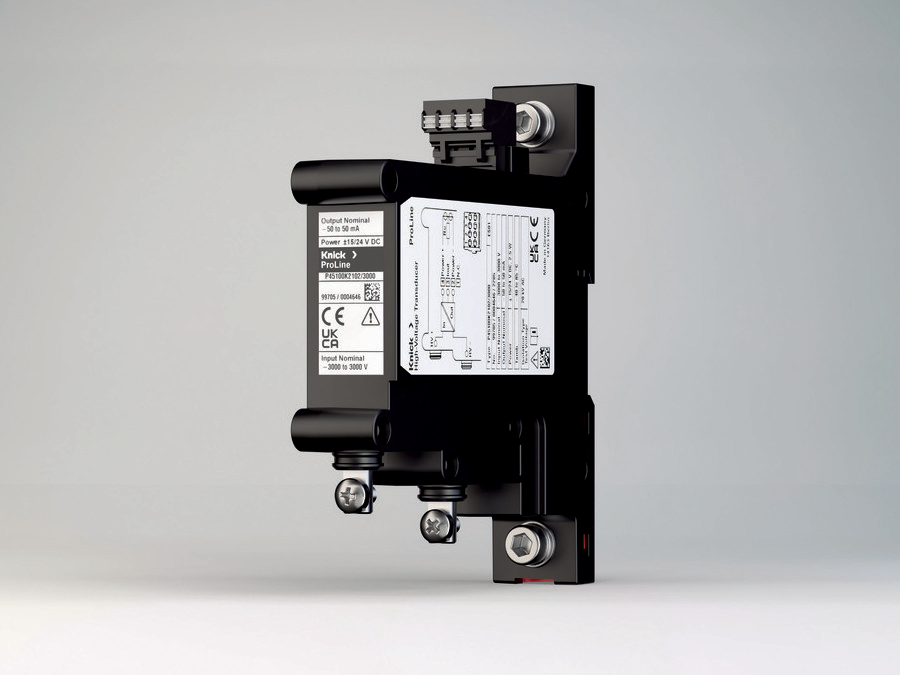
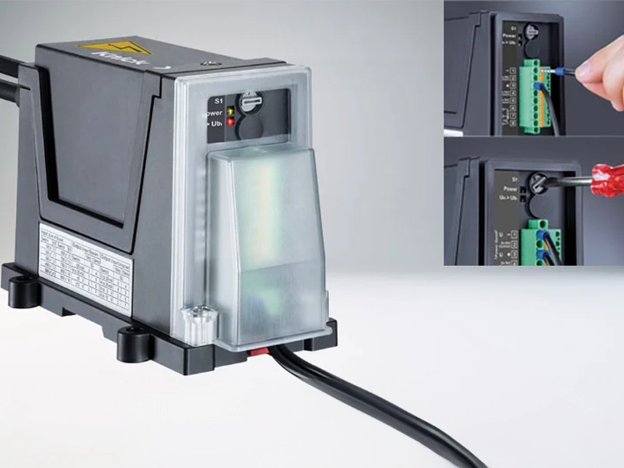
Adapted P45000 high voltage transducer as isolation barrier
On the current collector systems of certain locomotive series, proximity sensors verify the correct positioning of the contact shoe. Under adverse conditions, the sensors may come into contact with the third line. In such cases, this may lead to the destruction of the proximity sensors and to the transmission of the traction voltage to the rolling stock control system. Therefore, the sensor signal must be galvanically isolated from the analysis units.

Key facts about the application
Sector
Railway | Rolling Stock
Application
Galvanic isolation of a sensor signal on a potential of 750 V
Measured Parameter
24 V signals for transmitting the collector position (galvanic isolation of 24 V switching signals against 750 V DC)
Main Requirements
Safe isolation of the sensor connection to the rolling stock control system with a system retrofit
Description of application
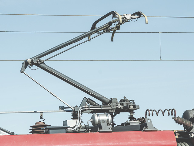
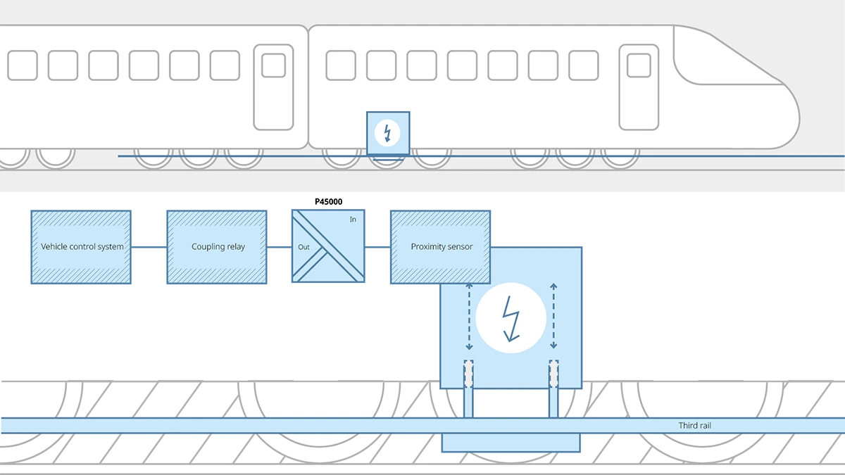
For dual-mode locomotives with collector systems for conductor rails, the contact shoes are positioned underneath the conductor rails and pneumatically pressed against their lower surface to make contact. An inductive proximity switch (24 V) monitors the vertical contact shoe position and transmits the lowered or raised position to the rolling stock control system via a coupling relay.
Requirements for the application
Due to its position, contact between the proximity sensor and the conductor rail cannot be ruled out. To avoid risks to the locomotive personnel and damage to the train control system, the sensor signal must be galvanically isolated.
Why Knick ?
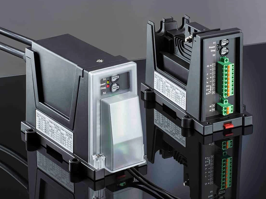
For the secured transmission of 24 V switching signals to the coupling relay, a high-voltage transducer in the P45000 series with basic isolation of up to 4800 V DC was adapted for signal transmission with switching characteristics.
In dual-mode locomotives, application-specific, adapted P45000 are used as isolation barriers between the control system and the current collector system
In railway networks that are only partially electrified or use different traction current systems, multi-system or dual-system rolling stock enables continuous line coverage without traction changes. While multi-system rolling stock can draw its traction current from different traction current systems, dual-system rolling stock has a bi-modal drive unit that is supplied from either diesel-electric power units or overhead lines. Dual-mode locomotives are a special form that have a contact system for conductor rails that run along the side of the line, alongside a generator with a diesel-electric drive.
Avoidance of Contact Between the Sensor and Conductor Rail with Potentially Serious Consequences
The collector systems of these locomotives position the contact shoes underneath the conductor rails and to make contact, press them against their lower surface via pneumatics. Inductive proximity switches (24 V) monitor the vertical contact shoe position and transmit the lowered or raised position to the rolling stock control system via a coupling relay. Since the proximity switches are located in the immediate vicinity of conductor rails with voltages of 750 V DC, under adverse conditions or in the case of mechanical defects, direct contact cannot be ruled out. Without an isolation barrier, a short circuit could not only destroy the proximity switch but in all likelihood could also destroy the coupling relay and the downstream control system. To limit the risk of damage to the proximity switches, one manufacturer looked for a simple, space-saving solution that could be integrated to protect the downstream electronics. With a P45000 high-voltage transducer adapted to the specific application, Knick was able to supply the ideal solution.
Solution
The high-voltage transducers in the P45000 series are certified in accordance with EN 50155 for use on rolling stock and designed to measure voltages between 500 V and 4500 V. In the present application, however, the transducers are only wired to galvanically isolate potentially destructive voltages between the proximity switches and the coupling relay. For the secured transmission of the 24 V switching signals to the coupling relay, Knick chose a P45000 design with an input measuring range for ±500 V and adapted the standard transmission behavior of ±500 V/±50 mA to signal transmission with switching characteristics. As the customer requested, Knick also replaced the bipolar 15/24 V power supply of the P45000 integrated as standard with a unipolar 24 V power supply. The solution has proven its worth. Thanks to the high basic isolation of up to 4800 V DC, test voltage resistance of 10 kV, and reinforced isolation of up to 2300 V DC between input, output, and auxiliary power, the high-voltage transducers in this application provide maximum protection for people and the control system. In addition, the high-voltage transducers met an important customer criterion for space-saving system integration with their slim design and housing width of only 28 mm.


