P16800 Duplicateur/convertisseur de signaux de vitesse universel | Découplage SIL 4 sans rétroaction des signaux des sondes de régime/de vitesse | Transmission sûre selon SIL 2
Description
Duplication, conversion et isolement de signaux de capteurs de vitesse
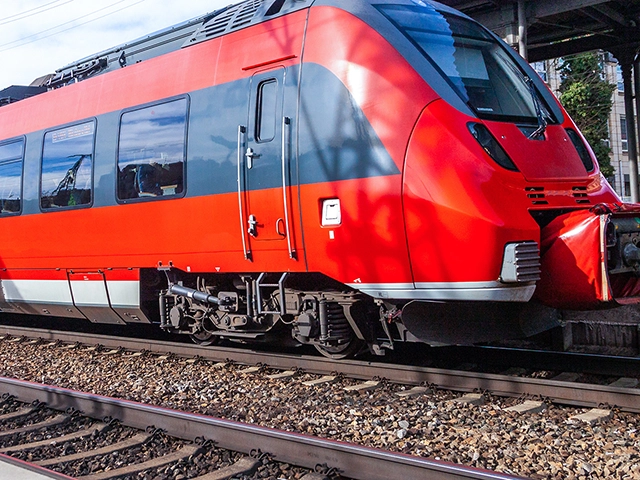
- Duplication des signaux de vitesse et donc simplification de l'intégration du système dans les véhicules ferroviaires
- Conversion optionnelle du signal de vitesse, augmentant ainsi la compatibilité des capteurs de vitesse
- Séparation galvanique du signal de vitesse et donc protection des composants en aval
- Traitement des signaux avec la sécurité fonctionnelle requise selon EN 50129 (SIL 4 et SIL 2)
- Boîtier compact pour montage en série sur rail DIN ou fixation murale
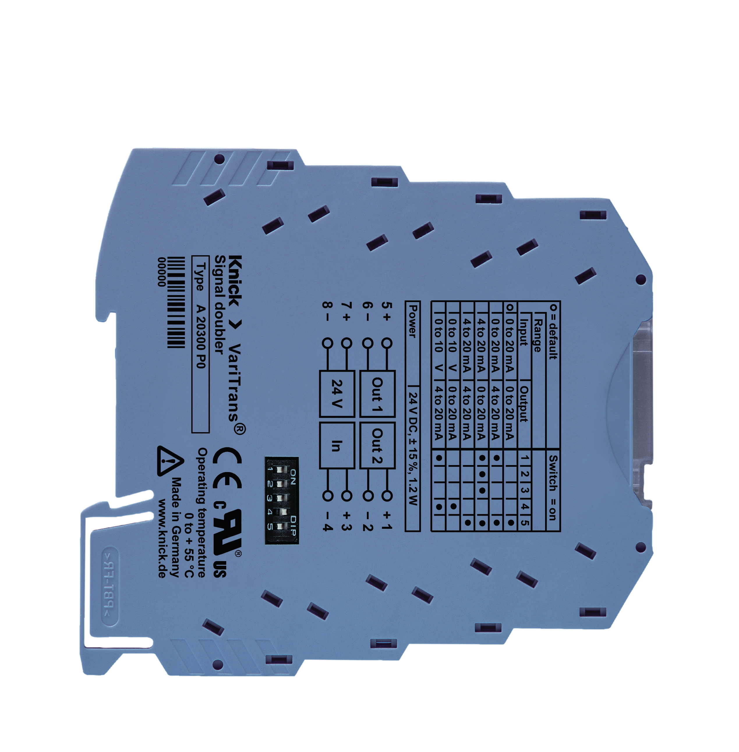
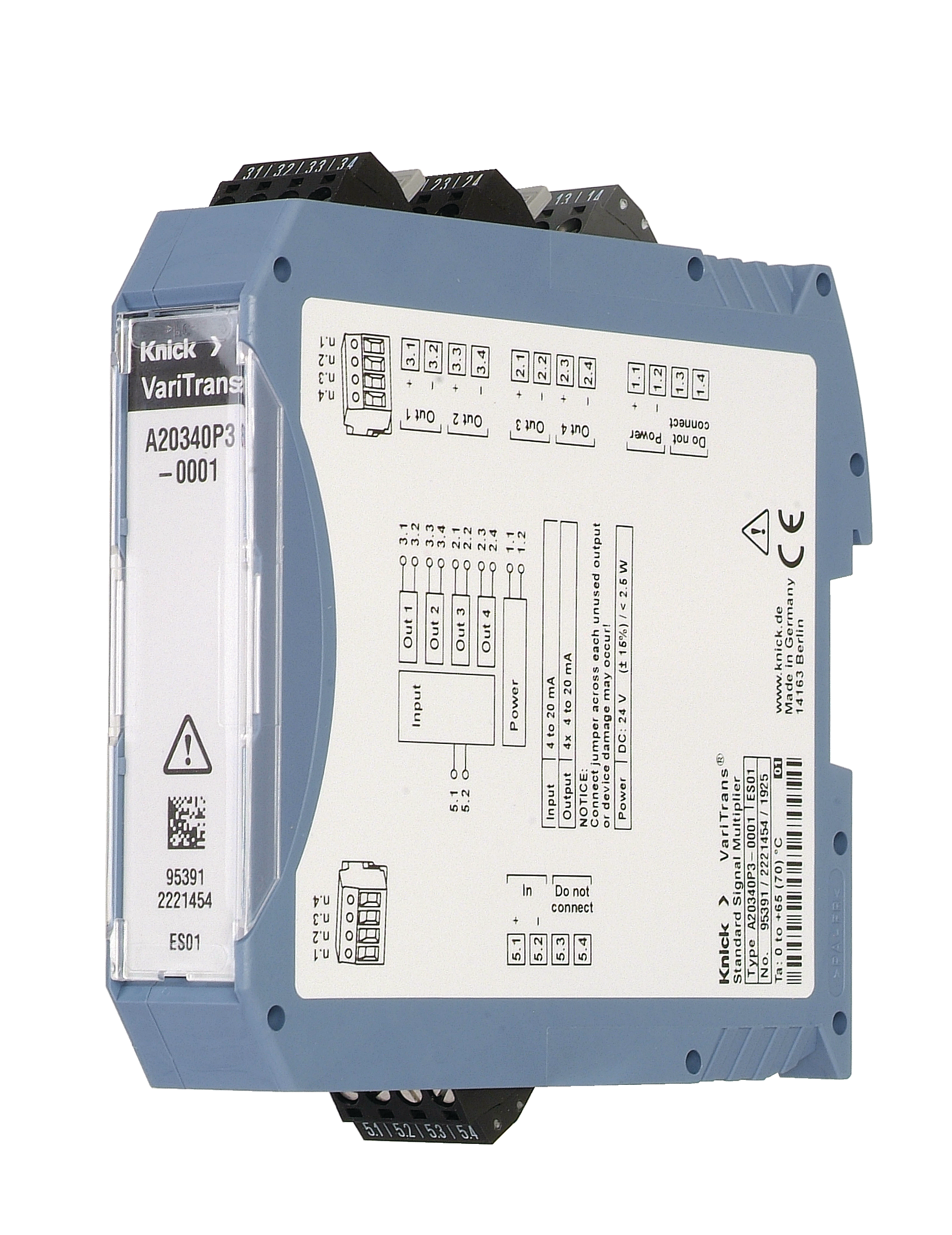
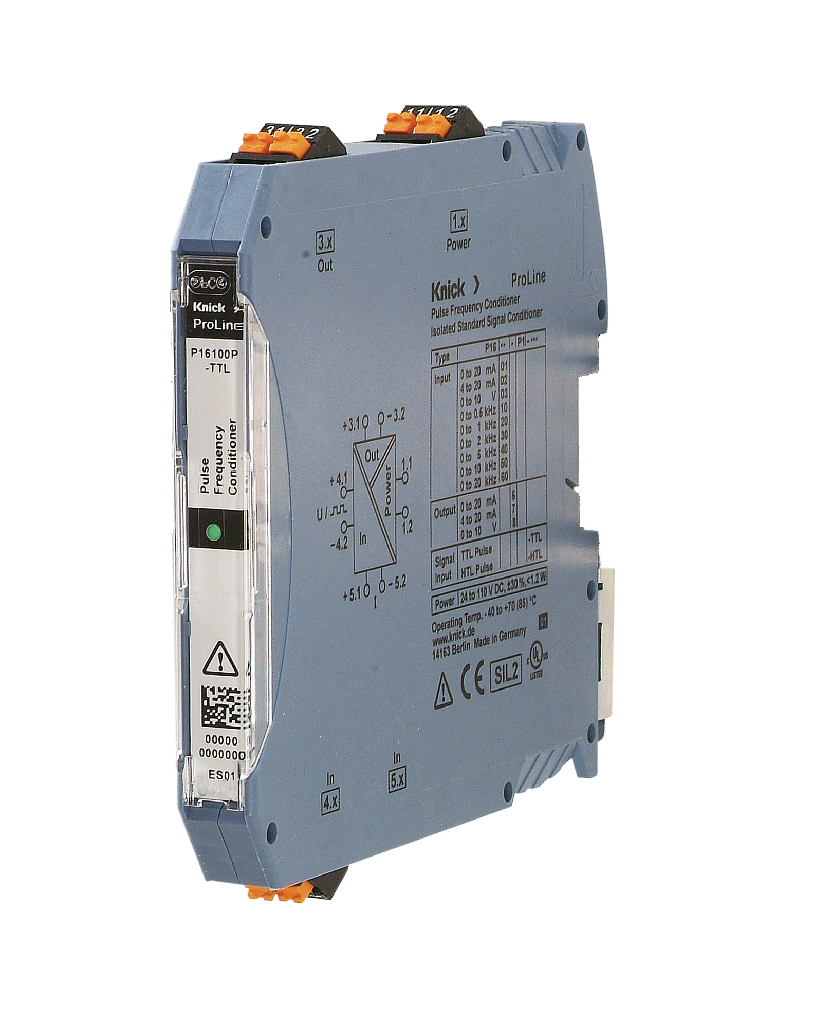
Le duplicateur de signaux de vitesse P16800 permet de dupliquer les signaux des capteurs de vitesse. Il découple le signal des capteurs de vitesse à un ou deux canaux avec la sécurité fonctionnelle requise et sans rétroaction, conformément à la norme EN 50129 (SIL 4). Les impulsions sont transmises 1:1 de l'entrée à la sortie, c'est-à-dire que la fréquence et la position de phase restent inchangées. La transmission des signaux des codeurs présente également la sécurité fonctionnelle requise selon EN 50129 (SIL 2), le P16800 assurant en outre une séparation galvanique des signaux. Pour la commande raccordée, les sorties du P16800 apparaissent comme un codeur. Tout comme les codeurs, le P16800 est alimenté en énergie par la commande raccordée.
Si nécessaire, le signal peut être converti d'un signal de courant en un signal de tension ou d'un signal de tension en un signal de courant. En option, il est possible de réduire la fréquence à la sortie par rapport à l'entrée dans un rapport de 2:1, 4:1 ou 8:1.
L'utilisation du P16800 simplifie l'équipement ultérieur de véhicules ferroviaires avec des commandes nécessitant des informations sur la vitesse ou rend un tel équipement ultérieur possible. Cela permet en outre de réduire le nombre de capteurs de vitesse sur les nouveaux véhicules, contribuant ainsi à optimiser les coûts d'acquisition et d'entretien.
Innovations at InnoTrans 2024 for rolling stock and DC traction power supply
sept. 2024
Interface Technology
Nous attendons avec impatience votre réponse!
Nous Contacter
| Séparation des potentiels CA/CC: | Jusqu’à 1 000 |
|---|---|
| Fonction: | Traitement des signaux des sondes de régime/de vitesse |
| Entrée: | Signaux de sonde de régime 6/7 ... 14/20 mA (200 mA maxi.) avec minimum : < 8,5 mA, maximum : > 12,5 mA, Signaux de sonde de régime 10 ... 33,6 V CC (35 V maxi.) avec minimum : < 30 %, maximum : > 70 % |
| Sortie: | Faible : , Min. 6 mA, max. : 14 ou 20 mA, Sens de la marche (DOT) – uniquement une sortie |
| Tension d'essai: | Jusqu’à 8,8 kV CA |
| Alimentation en tension: | 12 ... 24 V CC (UB) |
| Température ambiante de service: | -40 ... 70 °C |
| Dimensions (l x L x H): | 28 x 142 x 118 mm |
| Caractéristiques particulières: | Conversion en option des signaux de la sonde de régime, Duplication des signaux de la sonde de régime, Découplage sûr selon SIL 4, transmission sûre selon SIL 2 (EN 50129), Immunité CEM élevée |
| Standards: | EN 45545-2, EN 50129, UL 61010-1 |
| Catégorie de produits: | Convertisseur de mesure, Multiplicateur de signal |


